You're here: Main page > 2.3. Direct current supply and trolleybus overhead
2.3. Direct current supply and trolleybus overhead

The trolleybus network and current supplies were renewed at an expenditure of 3,6 millions
DM in the years 1990-1997.
The trolleybus operates with a rated voltage of 600 V direct current.
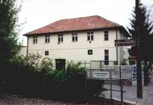
Three electric rectifier substations make the current supply from the
public network. The electric rectifier substations are equipped with 3 1000 KVA transformers
and 3 silicium electric rectifiers.
Into the trolleybus network are inserted 5 switches, 4 intake switches, 7 crossings, 19 disconnecting places (places without voltage), several crosswise
clutches and 11 supplies of direct current.
The trolleybus network is approx. 44,6 km long and structured after the so-called Lombard
system. Thus two contact wires run parallel to each other. Going in the driving direction
the left contact wire is plus-polarized; accordingly the right contact wire is minus-polarized. The contact wire consists of solid copper wire 12 mm in diameter. The trolleybus overhead network is installed at a height of 5,5 m over the roadway. In some places, e.g. in the proximity of traffic lights, the trolleybus overhead network was lowered on 5,3 m over the roadway.
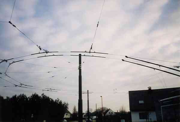
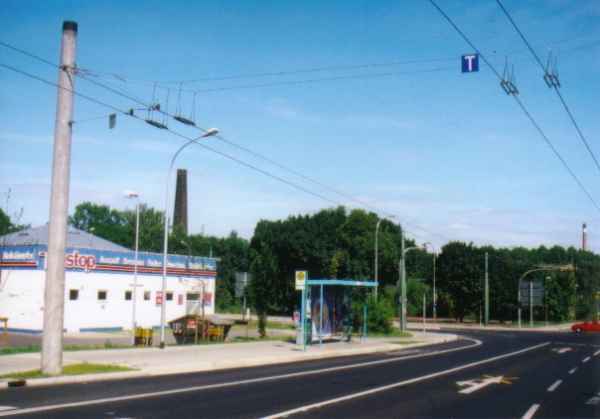
Here is a picture of the turnaround loop of the trolleybus network at the final stop Ostend:
The electronic switches are of the type U-88 of the Kummler+Matter company
Zürich/Switzerland. The mechanical structure consists of two modules, the switch module
and the drive module.
The switch module carries only the connecting pieces and the tongue of
the switch. When worn these are easily removed and replaced. By an easy adjustment the
position of the connecting pieces and the tongue of the switch can be moved to the left,
right or centered.
The drive module carries the necessary sections for drive and the monitoring units.
The drive magnet has two switching modes. Thus the switch can be used with or without
resetting of the tongue.
In the trolleybus network of Eberswalde the switches are used with automatic resetting of
the tongue. A monitoring unit at the drive magnet inductively sends the position of the
tongue of the switch. For the automatic resetting of the tongue the necessary signal comes
from a non-contact inductive sender.
In the drive module is integrated a control unit. This receives the switching impulses from
the trolleybuses.
The switches have an electronic direction signal, which displays the position of the switch
to the trolleybuses drivers.
The manufacturer claims that one can drive on the switches at high speeds (50-60 km/h).
However there were bad experiences in Eberswalde. After several heavy damages it was
determined that the safe rate for driving on the switches to be 15-20 km/h. The true reasons
for the several heavy damages are unknown.
The switches of the trolleybus network are controlled by the driver of the trolleybus. A
switching contact rail is added to the trolleybus network before each switch. If the driver
of the trolleybus wants to switch the trolleybus network switch, he operates a switch, which
briefly switches on the trolleybus's heating system (a large power consumer). Current must
be drawn when driving on the switching contact rail. If the driver of the trolleybus does
not want to switch the trolleybus network switch, he operates another switch that switches
off the high voltage system of the trolleybus. Thus no current is drawn when driving on the
switching contact rail, and the trolleybus network switch does not switch.
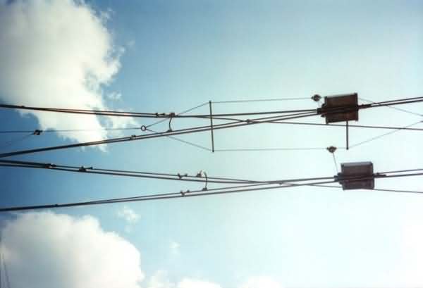
Picture: Switch at the branch to the depot Nordend
To switch the trolleybus network switch or not requires a little practice. The correct
switch must operate at the right time in the correct place with approx. 10-20 km/h
(considering other traffic). If it does not operate correctly the driver must take work
gloves and go to the rear of the trolleybus to put the current collectors (trolleys) onto
the correct wires by hand.
Intake switches are switches of the trolleybus network, which are mechanically switched by
the end pieces of the current collectors (trolleys). This takes place without action by the
driver of the trolleybus.
Picture: Intake switch in Nordend, Poratzstraße
Crossings are crossings of the contact wires. In order to avoid short-circuit, insulating
material is used, which leads the end pieces of the current collectors (trolley's). When
driving on crossings the accelerator may not be operated and the maximum speed must not be
exceed by 15-20 km/h.
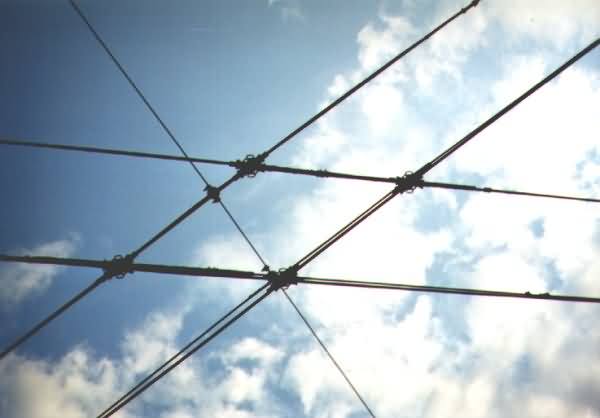
Picture: Crossing at the depot Eberswalde/Nordend
Disconnecting places are dead places (places without voltage) in the trolleybus network,
which serve to separate the supply of direct current of the different sections.
The planners and designer of the trolleybus network made some serious mistakes with these
dead places. Some of the disconnecting places are in the area before crossings with traffic
lights, directly on road crossings and in places in which one actually needs full current
when starting. Sometimes it is a feat not to be stopped on a disconnecting place. Also
the driver of a trolleybus must concentrate on the traffic. There are times when one must
stop on a disconnecting place. Try to explain to another motorist that the driver of the
trolleybus leaves a gap in the traffic for the necessary momentum for getting through the
disconnecting place. The other motorists think the driver of the trolleybus is
"asleep" and drive their cars into the gap, and the driver of the trolleybus must
brake.
With a trolleybus of the Hungarian type Ikarus 280.93 the driver of the trolleybus then has
a problem. This problem might be solved by pushing the trolleybuses, with muscle power, about 5-10 cm forward or backwards
. In this case the driver of a trolleybus of the Austrian type ÖAF-Gräf & Stift NGE 152 M17 switchs on the
emergency power generator.
The accelerator may not be operated when driving on disconnecting places.
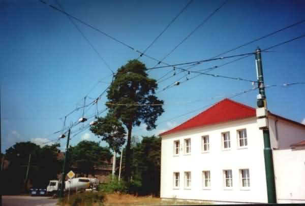
Picture: Disconnecting places in the Spechthausener Straße
Crosswise clutches are electrical connections of the respective minus or plus contact wires
of the trolleybus network of the "there and back" directions. A crosswise clutch
serves to balance the different electrical loads of the trolleybus network between "
there and back" directions.
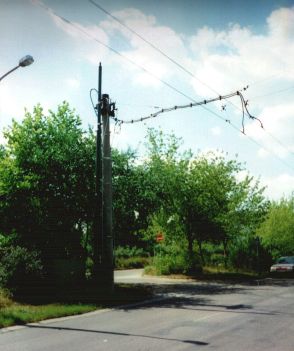
Direct current connections are places in the contact wires, into which is fed the 600 V
direct current to the trolleybus network that was produced in the electric rectifier
substations. In order to compensate for load, resistance and voltage fluctuations in the
trolleybus network, it is fed at several direct current connections, which are approximately
1-1.5 km apart. The direct current connections receive the current over ground cables from
the electric rectifier substations. The ground cables have a total length of 54 km.
The picture at the left shows the direct current connection in Nordend, Neue Straße.

